Loading...
Loading...
Loading...
Loading...
Loading...
Loading...
Loading...
Loading...
Loading...
Loading...
Loading...
Loading...
Description of Autonomous Control Engine purpose
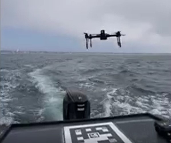
ACE™is an embedded flight control system from Planck Aerosystems that enables intelligent autonomy capabilities for unmanned aircraft missions that must operate from moving platforms, where there is no room for error and no substitute for reliability. Much more than a positioning system, ACE is a full-fledged control system that adapts to the conditions and motion of the ground vehicle or vessel, replicating the actions that would be performed by a highly skilled pilot.
ACE doesn't just tell the autopilot where to land. It determines how to land.
ACE is an add-on module that augments the flight capabilities of the aircraft. It works with the autopilot to provide autonomous outer-loop control.
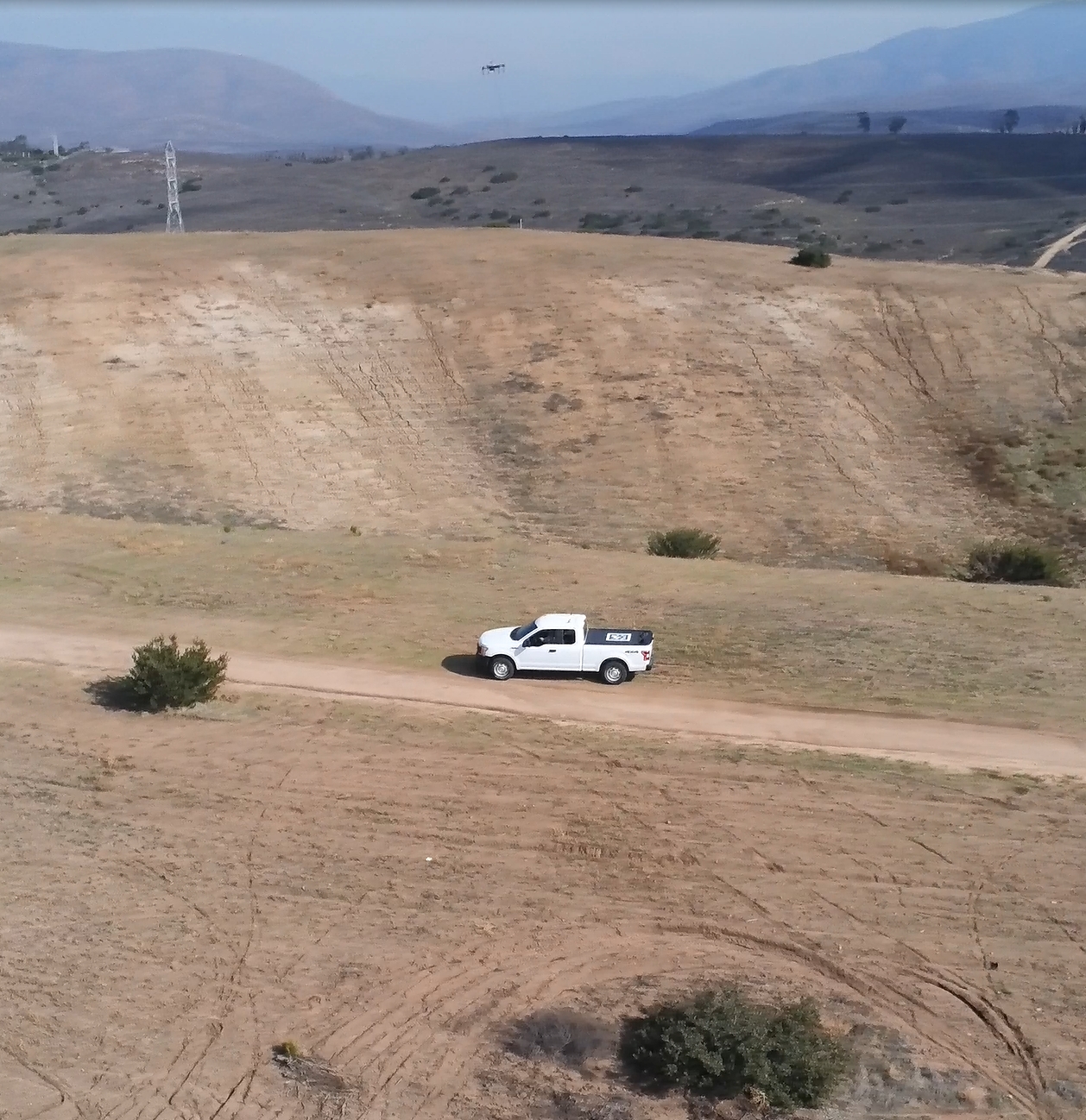
With thousands of flights from trucks, combat vehicles, small boats, and ships, ACE is a mature and trusted autonomy engine for some of the highest performance sUAS in the world. ACE forms the core of Planck’s navigation solutions for highly autonomous drone operations from moving vehicles and vessels.
ACE is a sensor-guided navigation solution that provides outer-loop control, intelligent behaviors, and specialized failsafes for UAVs, including precision landing without GPS. ACE is highly configurable to accommodate different types of aircraft, applications, and flight modes. ACE can also be configured in a guidance-only mode, providing relative position measurements and estimates instead of closed-loop control commands.
ACE is designed for UAS manufacturers who need a robust, high-reliability, tested, and proven capability for their defense and industrial aircraft. ACE runs on low SWAP embedded computer hardware onboard the UAV that is interfaced to the autopilot system to provide full control of the aircraft during critical phases of flight. ACE uses a downward vertical-facing camera for guidance during takeoff, landing, and precision station-keeping on the move, even with a complete loss of communication and/or GPS. Modes and missions can be configured through an adaptable user interface.
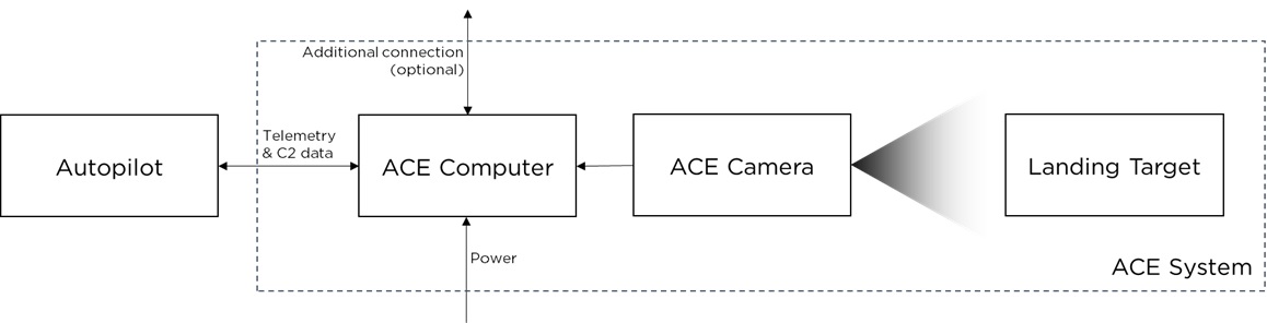
ACE interfaces
ACE requires an embedded computer connected to a small camera. A passive fiducial target is used on the ground to designate the landing site. For GPS-enabled operations, ACE includes a ground-based GPS which connects to the Ground Control System (GCS) for relaying the position of the landing target to the aircraft while the aircraft is out of visual line-of-sight of the fiducial target. Planck provides all required hardware components for a standard implementation.
In the standard implementation, ACE runs on a standalone processor to ensure reliable, secure operation.
Complete details for the system components is provided to customers in an interface control document (ICD).
Details of the hardware components are included in this page. Non-standard or customized implementations may be supported. For example, contact Planck directly for options to deploy ACE on existing UAV computers or cameras.
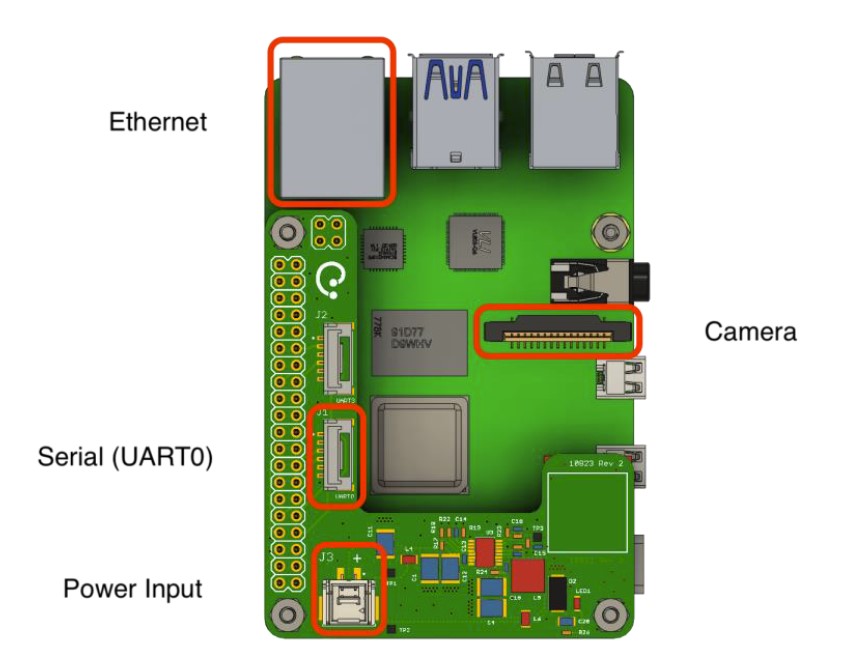
The embedded computer requires power provided by the drone. The supply voltage is regulated onboard. A cable is provided with the ACE module.
The ACE camera is powered directly from the computer, and no additional power connection is required.
The embedded computer has a bi-directional data interfaces with the autopilot via a serial connection in the standard configuration. For alternative interfaces, such as Ethernet, contact Planck. ACE is compatible with many autopilots and ground control stations. Alternative data interfaces and messaging formats can be supported through Planck's customization options.
The ACE camera interfaces directly with the computer, and no additional data interfaces are necessary.
The ACE module includes an embedded computer, small camera, and associated cabling. The computer, camera, and autopilot should all be mounted so that that cables lengths are minimized and free of electrical or mechanical interference.
The ACE camera must be mounted in a downward-facing vertical configuration that is free from obstructions. It should be rigidly mounted with the same rigid body that the autopilot is mounted within. For example, the camera may be mounted on the drone arm or fuselage, but should not be mounted on retractable landing gear.
ACE commands the aircraft using flight modes that require sending special MAVLink messages back and forth to the UAV autopilot. Planck provides custom open-source ArduPilot firmware for to support the custom messages and ACE flight modes. All existing open-source flight modes continue to be supported, and the custom version is only to support ACE-specific modes and messaging.
ACE uses a proprietary visual fiducial target system to assist with precision landing, takeoff, and station-keeping. Planck provides a landing target on a lightweight, folding material for easy stowage and transportation.
The information below is for the landing target provided by Planck. Customers may wish to use a smaller or larger landing target, or alternative materials, based on their specific application and aircraft size.
For night operation, the landing target must be illuminated with visible or near-infrared light.
Parameter
Specification
Supply Voltage
7 - 42 Vdc
Power (steady state)
4 W
Power (peak)
15 W
Connector
Flying leads (300mm)
Parameter
Specification
Connection
Serial
Type
3.3V TTL
Connector
6-pin JST-GH
Pinout
Complies with Pixhawk standard
Message format
MAVLink 2
Ethernet
RJ45 (Ethernet use is optional)
Parameter
Specification
Computer dimensions
89 x 59 x 26mm
Computer weight
71 grams
Mounting
4 hole pattern
Distance from autopilot
less than 300 mm (recommended)
Parameter
Specification
Camera dimensions
25 x 24 mm
Camera weight
3 grams
Mounting
4 hole pattern
Mount location
less than 50 cm from drone
center of gravity
less than 300 mm from
the computer
Mount height
5 - 100 cm above ground
Camera power interface
Provided by computer
Camera data interface
Provided by computer
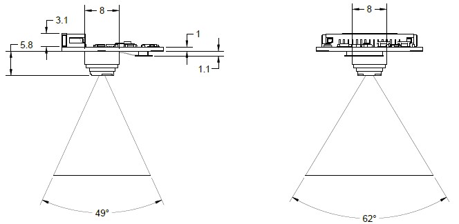
Camera field of view
62 x 49 degrees
Parameter
Specification
Size (open)
76 cm x 76 cm x 0.3cm
Size (folded)
56 cm x 56 cm x 0.6cm
Material
Aluminum composite
Weight
Approximately 2.2kg
Mounting
Multiple mounting options
Explanation of the internal workings of the Autonomous Control Engine
ACE can be used for either Full Control of the UAV from moving platforms, or in a Guidance Only mode that provides relative position information instead of control commands to the autopilot.
ACE uses a small camera and an onboard embedded computer connected directly to the autopilot to provide autonomous outer-loop control of the entire aircraft. ACE works by fusing measurement from the camera sensor with telemetry from the autopilot to resolve a navigation solution, and then sends commands to the autopilot to control the aircraft as needed to complete its mission.
ACE's operation extends beyond simply detecting a landing location. ACE's functions fall into three broad categories, which are all interdependent.
Sensor fusion and data processing
Predictive motion
Intelligent command and control
While ACE has several flight modes that use all of these functions, the most conspicuous is precision landing on moving platforms. We will use landing as the example for describing how ACE works.
ACE processes sensor data from the autopilot as well camera imagery, and fuses the measurements to determine the lateral position, range, pitch, roll, and yaw between the aircraft and the landing target.
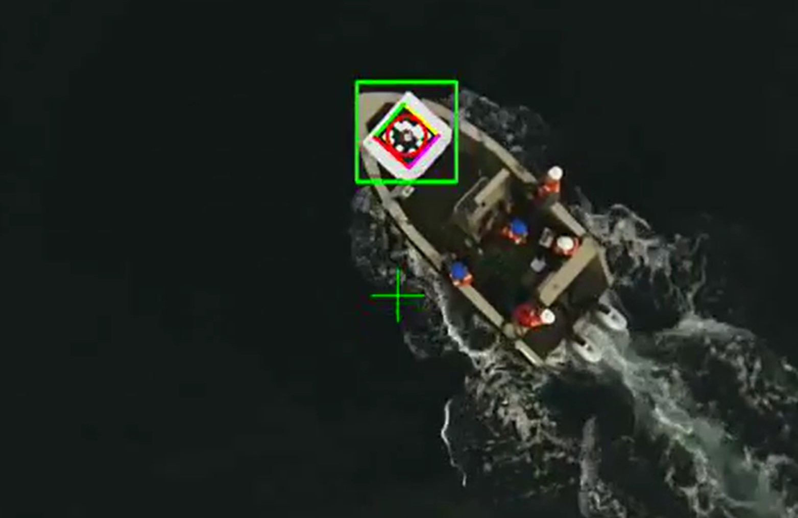
ACE uses a proprietary machine vision fiducial detection system that includes a code printed onto the landing target. The detection algorithm is very fast, and the landing target is detected and decoded at a high frame rate on the embedded processor. The detection system is robust to partial occlusions, changing lighting conditions, glare, blurriness, and moderate focus issues. The detection system also works in darkness with the aid of IR illumination on the landing target that is invisible to the naked eye.
By processing the fused data, ACE is able to lock onto the landing target as the aircraft approaches the host vehicle.
A predictive motion algorithm uses the outputs of the detection algorithm to predict the motion and future state of the aircraft and landing target. The motion is constantly updated to account for rapid changes and inaccurate measurements. The algorithm allows the aircraft to adapt to moving landing target very quickly in much the same way a highly-skilled pilot would make adjustments in a manned helicopter. In the terminal phase of flight, ACE determines the proper descent rate, and then finds the optimal time to execute a landing. ACE dynamically adjusts to conditions and prevents landing if the motion is too severe.
Based on ACE's sensor fusion and motion prediction algorithms, it generates precision controls and sends commands directly to the autopilot. The control algorithm is used to command the aircraft during any phases of flight specific to operations to and from moving platforms (e.g. takeoff, return-to-boat and landing).
The control system will adapt to the environment by changing the flight commands based on the landing target motion. It scales the flight characteristics based on its distance from the landing target. For example, it will track a boat more loosely at higher altitude, but respond more quickly when close to the landing target.
The control system executes maneuvers based on the state of the aircraft and landing target, which includes position and speed, in addition to roll, pitch, and heave. If a safe landing can not be executed, ACE will command the aircraft to hold position and wait for the landing target motion to stabilize. If necessary, it will command the aircraft to ascend and re-attempt an aborted landing, the same way a skilled pilot would.
During the critical terminal landing sequence, the algorithm will intelligently explore work to maximize landing reliably and accuracy. Timing is a crucial aspect for the landing maneuver to maximize precision. Reliability is prioritized to prevent mishaps that are common in other positioning systems.
Finally, ACE automatically detects when it is has landed and issues a motor shutdown command to the autopilot.
Flight behaviors and ACE system specifications
ACE is capable of detecting a wide range of fiducial target sizes and patterns. The size of the fiducial directly affects the maximum altitude at which ACE can reliably detect and track the landing target. Planck offers a standard 76cm target which affords an 20m+ detection altitude, though various parameters of the system can be changed to increase detection altitude at the expense of speed. Contact Planck for custom target sizes and configurations for increased detection altitude.
For a default configuration in normal lighting conditions, ACE will detect the fiducial target at 20-30hz, and provide updates to its internal estimator, or the autopilot in the case of Guidance-only mode, at 100hz (configurable).
During takeoff, the aircraft will ascend directly above the landing target until it reaches is maximum tracking height that is free and clear of obstructions on the vehicle or vessel.
The aircraft ascends most rapidly immediately after takeoff, before settling into a constant rate. During the ascent, the aircraft will also adjust yaw to maintain the same relative heading as the vehicle or vessel it is tracking (configurable).
Ascent Rate: 1 m/s (default), 0.1 m/s - 2 m/s (configurable)
*higher takeoff altitudes may require GPS and additional configuration
During landing, ACE will position the aircraft directly above the landing target from its approach altitude, yaw the aircraft relative to the landing target, and then descend and execute the landing maneuver. The descent rate will vary based on operating conditions, including wind and motion of the landing platform. At the very end of the sequence, the aircraft will descent very quickly.
*higher approach altitudes may require GPS and additional configuration
** The ideal fast descent altitude is different for each aircraft and scenario and should be configured accordingly.
At the end of a mission, or when commanded, the aircraft will turn toward the host vehicle and traverse a course that is optimized to minimize flight time while intercepting the moving landing platform. The intercept course is continually updated based on the motion of the host vehicle. Depending on the speed and direction of the host vehicle, the aircraft will adjust its heading and speed as it approaches, before transitioning to land.
The transit rate during the RTB portion of flight can be configured based on the aircraft capabilities and mission profiles.
In Wingman mode, the aircraft will hold a position (bearing and range) relative to the host vehicle as it moves. The aircraft will match the speed and direction of the host vehicle. However, in many cases it may be possible for the host vehicle to exceed the speed capability of the aircraft.
GPS is not required for ACE takeoff and landing operations from moving platforms. Standard GPS or other localization method is required for RTB, Wingman, and waypoint flight.
For tethered operations, GPS is not required for precision station-keeping. However, the operational envelope may be extended with GPS during tethered operations.
ACE is compatible with terrain models for flying in diverse terrain if supported by the autopilot.
The specifications in the table below are typical for ACE integrated into a UAV in a standard configuration. These assume that the aircraft has been carefully tuned for optimal performance and that ACE has been configured for the specific aircraft.
ACE includes failsafe behaviors are that specific for operating from moving vehicles and vessels.
ACE was developed over several years and thousands of real-world flights by experts in robotics, controls, and computer vision. UAS using ACE experience virtually no failed landings if within the operational envelope. ACE is intelligent enough to abort unsafe landings. Since it is more than a positioning system, ACE uses the state of the aircraft and landing platform, as well as timing, to execute landings at the right time. Planck has conducted thousands of UAV landings with >95% within 15cm of the center of the landing platform, even while moving. The vision-based navigation system is:
Robust to partial occlusions of the landing target
Adjusts to shadows and changing lighting conditions
Works in low-light conditions with visible or IR illumination
Robust to optical distortion, fuzziness, and difficult lighting conditions
The operational envelope is governed more by the performance of the aircraft than the ACE system. ACE issues very precise, high rate control inputs to the aircraft's autopilot, but it is up to the aircraft to successfully execute those commands. For example, the maximum speed of a boat during landing is a function of the maximum speed of the aircraft and the aircraft's control authority at that speed. The operational envelope for any given system should be determined through testing during the .
*ACE accounts for the heave of a dynamically moving landing platform, and it adjusts the descent rate accordingly. Timing the landing is crucial for safe and reliable operations, and ACE commits to a landing maneuver when the platform is within operational limits. If those limits are exceeded, the aircraft will perform a .
Parameter | Default | Configurable Range |
Ascent Rate | 1 m/s | 0.1 - 2 m/s |
Takeoff Altitude | 10 meter | 0 - 20+* meters |
Parameter | Default | Configurable Range |
Approach Altitude | 10 meters | 3 - 20+* meters |
Descent Rate | 0.5 m/s | 0.1 - 2 m/s |
Fast Descent Altitude | 0.7 m | 0 - 2 meters** |
Parameter | Performance | Notes |
Landing accuracy | 10 - 15 cm typical |
Vehicle speed during landing | 50% of UAV max speed | Includes relative wind |
Sea State | 3 on small craft | Rolling, pitching, and heaving* |
Target detection range | 20 m (65 ft) Option for 40m (130ft) | Range scales based on size of landing target |
Night operation | Yes - full operation | Requires visible or IR illumination |
Rain | Yes - full operation | Landing target must be visible |
Fog | Yes - full operation | Requires at least 20 meters visibility. Can be augmented with additional IR illumination or GPS. |
Failsafe | Behavior |
Loss of communications | Return to last known host vehicle location and hold position |
Low power | RTB and land on host vehicle |
Unsuitable Landing Location or Motion | Abort landing Hold relative position Ascend and restart |
Loss of landing target | Pause descent Ascend and restart |
ACE uses MAVLink messages for communication with the UAV autopilot and ground control station. ACE functionality can be integrated with any user interface that can send or receive MAVLink messages.
Planck provides a customized version of QGroundControl for ACE as a reference design. This can operate on Android, Windows, Linux or MacOS devices. It includes several useful features and enables all ACE functionality.
Vehicle-centric display, including a landing target indicator
Selectable ACE failsafe response behaviors
Range rings to determine bearing and distance between vehicle and aircraft (very helpful when flying from moving platforms)
Annunciator panel for aircraft health and status
Display for vertical camera video feed during landing (if enabled)
ACE provides a web-based user interface for configuring ACE and retrieving imagery and logs from flights. The web UI is made available via ACE's Ethernet or USB-C ports.
All of these functions can be ported to other ground control software by implementing the ACE-specific MAVLink messages and using the QGroundControl reference design as guidance. It is the UAV manufacturer or end-user's responsibility to test and support any custom ground control software.
Planck has experience using ATAK (Android Team Awareness Kit or alternatively Android Tactical Assault Kit). For specific UAV applications that require using ATAK, contact us to discuss integration options.
ACE includes several flight modes that perform specific functions when used. In a standard implementation, ACE has full control of the aircraft while being operated in one of the ACE flight modes. However, some customers prefer to receive precision guidance only, which can then be used by their own proprietary flight control algorithms.
This section includes brief descriptions of the flight modes. For additional description how the system behaves in various modes, refer to the Performance Specification.
In the full control configuration, ACE will send control commands to the autopilot when the UAS is being operated in one of the following ACE flight modes. The default GPS-based and manual flight modes that come standard with the autopilot (i.e. Loiter, Stabilized, etc.) are still available and are independent of the ACE system.
Precision takeoff from moving platforms with rapid ascent to clear obstructions. Continues to following the takeoff position and ascend to operational altitude. Does not require GPS.
Precision, vision-based landing on moving platforms without GPS. Intelligent descent based on motion and flight conditions, as well as landing maneuver to maximize reliability.
Return to base (RTB) optimizes a flight path to a moving host platform for a safe, smooth approach before transitioning to land. RTB requires GPS or other localization system.
Aircraft remains at a fixed position (bearing & range) relative to a moving host vehicle. Wingman requires GPS.
Precision station-keeping of a UAV over a moving vehicle or vessel for mobile tethered and pseudo-tethered operations with or without GPS.
When configured for Guidance Only, ACE provides very accurate, high-rate, filtered relative position measurements to the autopilot or other subsystem. Guidance Only configuration behaves as an open loop precision sensing module and does not issue any real-time control commands. Guidance Only may be useful for UAV operations from fixed locations, proprietary autopilots, or other unmanned vehicle types.
Large, heavy-lift multirotors for cargo delivery
Tethered drones for persistent ISR and comms relay
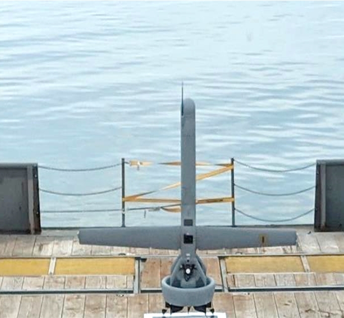
Fixed-wing VTOL (a.k.a. "quad planes") for shipboard flights
Tailsitters for maritime ISR
Single rotor helicopters
ACE provides outer-loop UAV control by sending low level commands to an inner-loop flight controller (autopilot).
ACE is natively compatible with Pixhawk and most other flight controllers running ArduPilot firmware.
ACE offers an open-source MAVLink-based API for integration into other autopilot software systems. Additionally, custom interfaces can be developed for different autopilots. Note that some features and capabilities may not be available when using alternative autopilots.
Radios must be capable of sending and receiving compatible data types, which can be ingested by the autopilot and re-routed to the onboard ACE system. Many compatible radios exist. For streaming video, a high bandwidth IP radio is recommended.
Common radios that ACE is compatible with are shown below. This is not an exhaustive list. Contact us to discuss options if your UAV uses a different radio.
MANET mesh IP radios
WiFi
Note: Planck does not manufacturer nor distribute any of these radios. This list is for informational purposes only.
In some cases, ACE has been used in conjunction with other UAV subsystems, such as sensor packages, object detection and tracking systems, and cargo/parcel delivery and retrieval systems. Planck can provide engineering support to adapt ACE to your mission needs.
Every drone is different. Every vehicle and vessel is different. Therefore, every integration of drones onto vehicles or vessels is unique. Planck has experience with tackling these challenges, and can provide engineering support to ensure mission success.
Examples of previous integration efforts include:
Boats as small as 7 meters (23 feet)
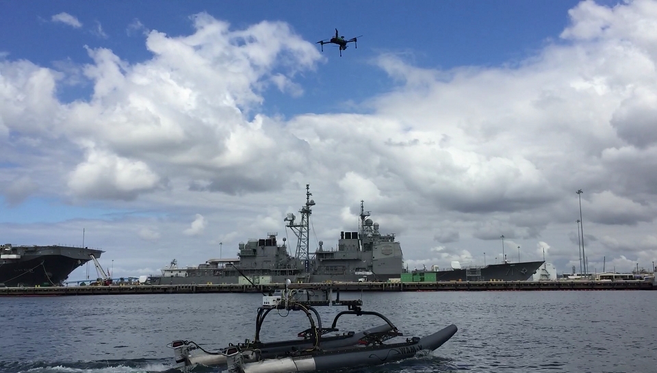
Unmanned vessels (USV) as small as 5 meters (16 feet) with remote operation
Ships from 30 - 100 meters (100 - 330 feet)
Commercial pickup trucks
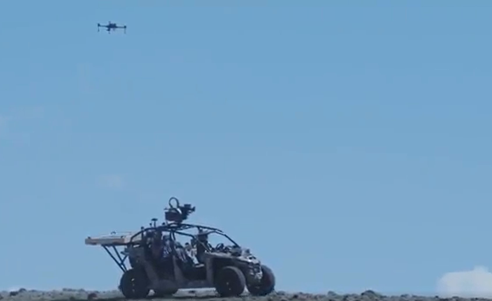
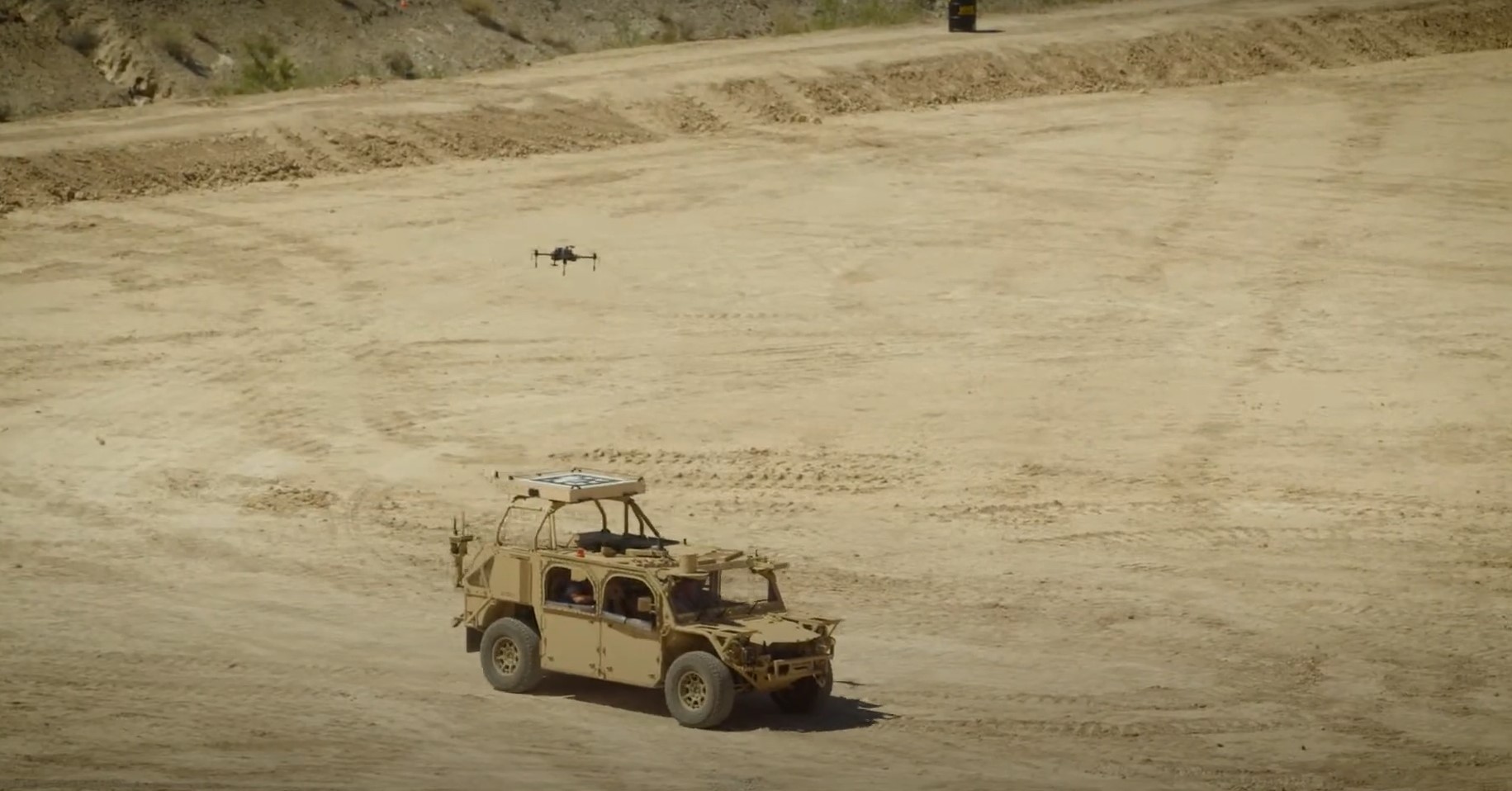
Off-road side-by-side (SxS) ground vehicles as small as 3.5 meters (11.5 feet)
Combat ground vehicles as large as 7 meters (23 feet)
Unmanned ground vehicles (UGV) with remote operation
ACE can provide precise, vision-based positioning without GPS for fixed wing aircraft during takeoff and landing maneuvers. ACE has also been used for GPS-denied positioning of unmanned underwater vehicles to address specialized mission needs.
ACE has been successfully integrated and operated by unmanned aircraft ranging from 0.5 kg to 70 kg (1lb - 150lb) in many different form factors. There is no functional limit to the size or weight of the aircraft for ACE to operate. While ACE is typically installed in aircraft with vertical takeoff and landing (VTOL) capabilities, it has as well. ACE has been used in:
Small multirotors, including
/
ACE has enabled drones to operate from many vehicles and vessels, each with their own set of constraints and opportunities. to help achieve you objectives.
When integrated, ACE becomes a critical part of your unmanned aircraft control system. It must be integrated, configured, and tested thoroughly. Refer to the ACE Component Specifications for details on the individual components.
Before installing ACE, the UAV should be well-tuned and tested. It should be capable of stable flight across the full range of operating conditions.
Integration and testing of ACE into the aircraft requires the steps listed below.
ACE provides integration flexibility. The camera and computer can be mounted in different locations based on aircraft and payload needs.
Planck provides customers with detailed integration guides and interface control documents (ICDs) to assist with this process. Planck can also provided engineering and test support as needed.
The computer can be mounted within our outside of the aircraft using 4 mounting holes. The computer should be mounted within 300mm of the autopilot and 300mm of the camera, although these can be extended if care is taken to minimize interference. The computer requires a power input, a serial connection the autopilot, and a ribbon cable to the camera. In some configurations, an Ethernet port may also be used.
Note that the computer is not provided within an enclosure and should be protected from any water/rain that may be encountered during a mission.
The camera must be mounted rigidly in a fixed downward-facing vertical position using the 4 mounting holes. It requires an unobstructed view below the aircraft. Ideally, the camera is mounted within 50 cm of the aircraft's center of gravity and within 300 mm of the computer. The camera is connected to the computer with a ribbon cable and does not require additional power. For aircraft with high vibration levels, the camera may be mounted on vibration isolators.
Note that the camera is not provided within an enclosure and should be protected from any water/rain that may be encountered during a mission. Typically, this is done by mounting the camera within the fuselage and providing a small 1cm hole for the camera sensor.
For autopilots with ArduPilot firmware, Planck provides open-source custom firmware to enable ACE modes and telemetry. This should be installed on the autopilot. All existing ArduPilot functionality remains unchanged.
For other autopilots, including proprietary flight controllers, contact us to discuss interface and integration options.
The system must be configured for each specific aircraft type. ACE includes a browser-based interface (Web UI) to easily access and adjust the configuration parameters. Most ACE parameters can also be modified via the MAVLink parameter protocol.
The autopilot firmware must also be configured to interface with ACE so that data can be passed between the two subsystems. This can be done with any compatible ground control software. Planck provides a specialized version of QGroundControl which supports the additional ACE-specific flight modes, failsafes, and mission items as well as offers feedback to the user about the state of the ACE system.
ACE requires a one-time calibration process for each aircraft type to ensure the camera is installed and adjusted properly. This calibration is in addition to any normal calibration and tuning required on your aircraft. Planck provides calibration instructions to customers. This calibration does not need to be repeated for subsequent integrations onto the same aircraft type.
The landing target designates the landing site for the aircraft. It can be mounted on any suitable landing location. It is recommend to attach it to a surface or structure if your aircraft generates enough downward prop wash that could blow the target away. Some customers may elect to permanently attach it to a structure using bolts, while others temporarily attach it using clips or adhesive. For testing purposes, the landing target may be laid on the ground.
A GPS receiver must be placed within 3 meters of the landing target. This receiver provides the position of the landing target to the aircraft during some flight modes that require it. The GPS receiver must be plugged into the ground control station so that it can be routed to the aircraft. The ACE system includes a GPS receiver for this purpose. The GPS receiver is not required for GPS-denied (e.g. tethered) operations.
Planck provides an open-source custom version of QGroundControl which can be used either as a reference design or for functional missions. If using different ground control software, it must be modified to enable ACE flight modes.
Testing is critically important prior to deploying any unmanned aircraft system. After the initial integration and configuration process is complete, Planck recommends the following testing regimes to gradually increase flight complexity without sacrificing safety.
Fly in an indoor safety cage (if possible) with a RC pilot backup
Fly from stationary locations at an outdoor test site with an RC pilot backup
Fly from a moving platform in controlled conditions with an RC pilot backup
Fly in a representative operational environment with RC pilot backup
Planck can provide engineering support for the installation, configuration, and calibration process. Planck can also provide testing support, including indoor and outdoor flight testing.
Engineering support can be either remote (via video conference, phone, and email) or in person, depending on location and availability.
Planck also provides engineering services for ACE customization and general UAV autonomy and controls development.
Contact us for more information about engineering support options.
Unmanned Autonomy with ACE
ACE is a technology solution for unmanned autonomy applicable to many different applications and use cases. ACE allows operators to advanced missions automatically, without the need for a dedicated skilled pilot. Each application may use a specific type of aircraft. The list below includes applications from existing customers that are enabled with ACE onboard.
Ship-based maritime ISR
Vehicle-based ISR
Tethered flight without GPS from moving vehicles
Drones operating from unmanned ground vehicles (UGV)
Drones operating from unmanned surface vessels (USV)
Ship-to-shore, shore-to-ship, and ship-to-ship delivery
Autonomous man overboard emergency response
Convoy support
Precision landing for remotely operated drones from fixed platforms
Parcel delivery and retrieval
Oceanographic research and maritime survey
Many government and commercial customers trust ACE for unmanned autonomy. Customers and integration partners include:
US Navy
US Customs and Border Protection
US Department of Energy
UK Navy
NOAA
MartinUAV
Parrot
Malloy Aeronautics
Lockheed Martin
Spektreworks
Kratos
Nordic Unmanned
AEgis Technologies
... and many other defense primes and commercial organizations
ACE system benefits compared to alternative approaches, as well as a list of limitations.
Safety features to support (or eliminate) a skilled pilot
Push-button launch and recovery from moving vehicles
Suitable drones of all sizes and configurations
Very low size, weight, and power on the aircraft
Minimal installed hardware on the host vehicle or vessel. Only requires a passive (unpowered) landing target.
No additional sensors required (e.g. rangefinders or other altimeters)
No need for special calibrations. Set it once and it never needs changes.
Works with tethered and free-flight systems
Reliable, even in RF noisy and GPS-degraded environments.
Jam resistant
Spoof resistant
Secure with encrypted software and no external connectivity
No data interface or knowledge of host vehicle is required. Only requires free and clear space to launch and recover the aircraft.
Compatible with terrain awareness system
Compatible with object detection and tracking systems
Portable to different computing hardware to future-proofing
Easy to use WebUI for configuration
Visibility required (10 meters)
Illumination (visible or near infrared) is required for night operation or very heavy fog.
GPS is required for some flight modes (but not landing, takeoff or tracking)
Not compatible with all commercially available autopilots
Operational envelope limited to approximately 50% of maximum aircraft performance (for example landing speed)
Frequently asked questions about the ACE system
ACE is intended for manufacturers of unmanned aircraft systems that wish to expand the scope of sales opportunities by offering their customers the ability to operate autonomously from moving vehicles or vessels on land or at sea.
ACE is also intended for end-users who operate fleets of aircraft and wish to take them off road or off shore.
ACE is specifically designed to provide autonomy for unmanned aircraft operating from moving vehicles and vessels on land or at sea. This is a very different challenge compared to operating from fixed, stationary locations, and solutions should not be considered interchangeable. ACE has been developed and tested over many years by experts in the field, and it has been validated through thousands of successful flight operations.
There are many other products available that provide precision positioning with different sensing modalities, effectively acting as a sensor input. In many cases, that is sufficient for landing on a stationary platform. In fact, ACE can be configured to provide only that capability without GPS and active RF communication, but most of our customers demand more.
If you are on a moving platform, especially when landing mishaps can not be tolerated, then ACE is the solution.
Since ACE is integrated into your aircraft and becomes part of the control system, it can be difficult to try out the way you might with an external payload. ACE is not a bolt-on payload. Like the rest of the control system on your aircraft, it must be integrated, configured, and tested thoroughly before it is ready to deploy.
Planck can provide demonstrations of ACE on other similar UAVs, but they might not be a perfect representation of your system or mission needs. We can also provide videos, virtual demonstrations, technical support, and references to successful integrations to third-party aircraft.
We understand that this requires an investment, but we're here to help you along with way. We've done dozens of integrations with a range of different aircraft types and sizes. The one-time engineering integration effort is worth it.
Camera and lens intrinsics and characteristics are very important for reliable operation. Changing the camera or lens will have impacts to system performance and is not recommended without coordinating with Planck. The ACE camera is a small form factor and very lightweight.
In some cases, an aircraft may already have a camera in place that is suitable for ACE. Planck can work with you to evaluate whether the camera will work, and the process to interface it with the ACE system. Contact us to discuss options.
ACE is natively compatible with most autopilots using ArduPilot firmware. That configuration provides the full range of capabilities provided by ACE.
Since ACE is not a payload or simple sensor input, it requires a direct interface with the autopilot and two-way communication.
ACE can be configured to work with other autopilots, including proprietary systems. In these cases, a limited subset of features may be available.
However, some third-party autopilots, including commercially available models, do not provide the interfaces necessary for ACE to operate.
The computer vision system is tolerant of occlusions, including blurriness from a limited amount of dust or water. However, the ACE camera should be kept clean and free from obstructions. The ACE camera is very small and easy to protect, and it should be mounted in a location to limit its exposure to dirt and water. In the standard configuration, ACE performs a pre-flight check to ensure that the camera is in good working order and will prevent the aircraft from taking off if the camera's view is obstructed.
All of Planck Aerosystems software is developed, stored, and controlled in the United States.
In most cases, ACE can be exported and integrated onto your aircraft. Contact us to discuss export options.
Yes, the underlying technology behind ACE is patented by Planck Aerosystems.
Planck Aerosystems is located in San Diego, California. We serve customers throughout the world. Please email us for ordering, technical inquires, and support in integrating and testing ACE with your aircraft.
Email: ace@planckaero.com
Phone: +1 619-230-5049 (may not be staffed due to COVID19)
Planck provides ACE and engineering support for integration, configuration, calibration, and testing of the system. After the initial integration process, identical ACE units can be quickly ordered and installed in the same aircraft type.
Contact us to start the ordering process. The ordering process includes:
Brief technical exchange to discuss interfaces and integration options
Evaluation of required engineering and test support (if any)
Formal quotation for ACE and any other services
Fulfillment / shipping initiated upon receipt of a purchase order
Engineering and test support is provided by Planck on a time and materials (T&M) basis with a fixed hourly fee. Some customers may require only minimal support, while others elect for extensive engineering and test support. It will depend on overall technical objectives, scope of the effort, the availability of internal engineering and facility resources, and state of the rest of the unmanned aircraft system. Through technical interchange meetings, Planck can provide an estimate on the amount of engineering support required to achieve your objectives.
Both on-site and remote support options are available. Remote support may include video conferencing, phone calls, email, and remote system access. On-site support may include physical integration, flight testing, and training.
In some cases, customized variants of ACE can be developed and maintained by Planck, and provided to customers pre-configured for their specific application or airframe.
In most cases, ACE is delivered with an embedded computer and small camera. As part of the UAV control system, deploying ACE software on other computers and with other cameras may have impacts to the system performance and functionality.
The most expedient path to use ACE is with the standard module, and we recommend this for all new aircraft integrations. Deeper integrations with existing UAV computers or cameras are evaluated on a case-by-case basis. These will require technical collaboration and non-recurring engineering effort. Contact us to discuss options and path for deep integrations.